




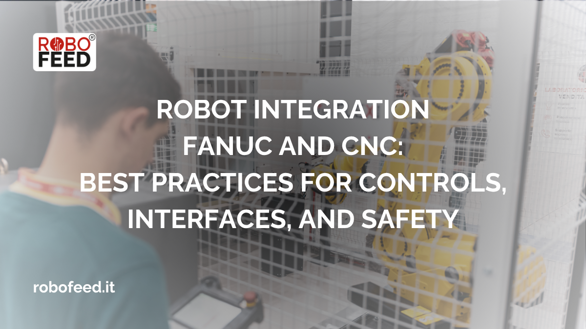
Integrating a Fanuc robot with a CNC machine is not simply a matter of connecting two control systems and exchanging a few signals. A truly effective integration must coordinate the robot, CNC, gripping systems, safety devices, and process logic, precisely defining which system controls each phase of the cycle and what conditions must be met before the cycle can begin.
For this reason, when designing a CNC-controlled system, the choice of interface and communication logic is just as important as the choice of robot. It is also essential to distinguish between the functions dedicated to cycle control and those used for monitoring and data collection.
Indice dei contenuti
ToggleWhat does it mean to integrate a Fanuc robot with a CNC?
In a typical follow-up application, the Fanuc robot performs operations such as:
- removal of the raw piece;
- machine tool load;
- unloading the machined part;
- management of grippers and gripping systems;
- handling to pallets, warehouses, or subsequent stations.
The CNC, on the other hand, controls the machining process and must signal to the robot when the machine is available, when the cycle is complete, and when certain operations can be performed.
Integration therefore serves to create a coordinated sequence of states and approvals, preventing robots and machines from operating as independent systems.
A good project begins by defining the production sequence and only then identifies the signals and interfaces needed to implement it.
CNC Interfaces and Communication Between Robots and Machines
Communication methods may vary depending on the installed CNC, the control system generation, the robot, and the available features.
Digital I/O and Handshake
Digital I/O is one of the most commonly used methods for managing the so-called handshake between the robot and the machine.
A simplified example might include signals such as:
- CNC ready;
- robot pronto;
- CNC cycle completed;
- load/unload request;
- robot in position;
- workpiece present;
- gripper closed/open;
- start authorization;
- robot alarm;
- machine alarm.
The fundamental principle is that every signal must have a unique meaning and a clearly defined activation condition.
It is not enough to simply specify that the robot receives a “load permission”; it is necessary to define when that permission can be generated, under what conditions it is valid, and what happens in the event of a cycle interruption.
Ethernet, fieldbus, and dedicated interfaces
When the application requires it, the integration can utilize industrial communication systems and Ethernet, including protocols and interfaces supported by specific FANUC configurations.
FANUC also offers various solutions for connecting robots to the CNC. These include functions dedicated to communication and integrated control, with the ability to display robot information on the CNC and vice versa.
However, the choice should not be based solely on the available protocol: the correct approach is to identify the architecture that ensures the level of communication, diagnostics, and safety required by the application.
CNC Commands and Robot Control
Another aspect to consider is how commands are managed between the CNC and the robot.
FANUC architectures include solutions that allow the CNC to issue commands to the robot or to use the robot as the central element in cycle management.
FANUC, for example, offers solutions such as Robot G-Code, which allows the robot’s movement to be programmed using G-code commands from the CNC, and Robot ON-SITE, which enables the robot to interact with the machine’s G-code program via a specific interface.
This type of approach can simplify integration in certain contexts, but it does not eliminate the need to properly design the system’s logic.
The question to ask, therefore, is not just “which control should I use?”, but:
Who should control that function, at what stage of the cycle, and under what safety conditions?
It is this logic that makes industrial integration robust.
MT-LINKi: What It’s Really For
MT-LINKi is FANUC software designed for connecting machines and for collecting, managing, and displaying production data. It can acquire information from FANUC CNCs, robot controllers, OPC UA-compatible PLCs, and other supported machines.
For this reason, MT-LINKi is particularly useful when the goal of integration is not only to automate loading and unloading, but also to make production cell data available.
It can, for example, help display machine status and analyze operational information.
However, it is important not to confuse this level with the cell’s primary interlock and safety logic: a data collection system does not replace the safety architecture required to coordinate the robot and the machine tool.
In a proper design, therefore, at least three levels must be distinguished:
- process control, i.e., the robot-CNC sequence;
- safety, i.e., the authorizations and shutdowns necessary to protect people and the equipment;
- data collection and monitoring, where tools such as MT-LINKi can play an important role.
Safety in Fanuc Robot and CNC Integration
Safety should not be an afterthought at the end of the project. It must be defined alongside the cell architecture.
The ISO 10218-2:2025 standard specifically addresses the safety of robotic applications and cells and covers design, integration, commissioning, operation, and maintenance. The assessment and mitigation of machine risks also refer to the principles defined by ISO 12100.
In a robot cell controlled by a CNC, the following aspects—among others—must therefore be evaluated:
- access to the work area;
- doors and interlocks;
- emergency stops;
- conditions under which the robot and machine stop;
- restart after an interruption;
- operator presence in the hazardous area;
- status of the gripper and workpiece;
- any loss of power or communication;
- alarm handling;
- manual mode, setup, and maintenance.
One particularly important point concerns restarting: closing a door or restoring a safe condition should not automatically be interpreted as consent to restart. FANUC itself emphasizes this principle in its safety guidelines.
Safety and communication are not the same thing.
This is one of the most common mistakes made when designing an integration.
A signal such as “robot ready” does not equate to a safety enable.
Process logic can determine whether the robot is in the correct position to begin an operation; the safety function, on the other hand, must ensure that the operation can be performed without creating hazardous conditions.
The two approaches must complement each other, but they must not be confused.
Best Practices for Reliable Integration
To design an effective Fanuc robot and CNC integration, it is helpful to follow some fundamental principles.
1. Define the Cycle Sequence First
Before programming the robot and CNC, you must describe the complete production cycle: initial state, loading, machining, unloading, inspection, fault handling, and return to the initial state.
2. Define a signal matrix
Each I/O or communication variable must have a specific function, an activation condition, and an associated response.
3. Explicitly handle errors
A robust integration must account for what happens when:
- the robot fails to reach the position;
- the gripper fails to detect the part;
- the CNC enters an alarm state;
- a door is opened;
- communication is interrupted;
- machining authorization is missing.
An error must not leave the system in an ambiguous state.
4. Separate Control, Safety, and Supervision
Process control, safety functions, and data acquisition must be designed as distinct but coordinated layers.
5. Plan for Diagnostics and Maintenance
An automated system must also be designed with the people in mind who will be diagnosing it months or years after installation.
Clear messages, signal documentation, up-to-date schematics, and recovery procedures drastically reduce downtime.
6. Simulate and test before startup
Simulation allows you to verify the sequence, identify conflicts, optimize movements, and arrive at the installation site with a design that has already been validated. This approach is consistent with that adopted by ROBO FEED, which uses simulation software to verify the solution before installation at the customer’s site.
Why Integration Requires CNC and Robotics Expertise
The most challenging aspect of automating a machine tool is not necessarily the robot itself.
The result depends on the interaction between the CNC, robot, PLC, grippers, sensors, safety circuits, and the production process.
It is precisely this cross-disciplinary expertise that allows us to work on existing machines as well, where the original control system, documentation, or architecture may impose specific constraints.
ROBO FEED stems from Assistec’s experience in providing electronic and mechanical support for CNC machine tools and develops robotic integrations that are designed, manufactured, and installed in-house. The service also includes consulting and post-installation support.
A concrete example is the project carried out for an older CNC machine with a Fanuc controller, which was automated using a compact solution featuring a FANUC collaborative robot and a retrofit of the machine tool.
Integration of Fanuc Robots and CNC: The Role of the System Integrator
Effective integration goes beyond the physical connection between the robot and the machine.
It requires an analysis of the application, the definition of the communication architecture, the design of cycle and safety logic, programming, testing, and commissioning.
For a system integrator or technician tasked with automating a CNC machine, the real goal is therefore not simply to make the robot and CNC “talk” to each other, but to build a system that is predictable, diagnosable, safe, and consistent with the production process.
ROBO FEED develops automation solutions for CNC machine tool tending, integrating Fanuc robots and systems designed to suit the process, available space, and production objectives.
Do you need to evaluate the integration of a Fanuc robot with an existing CNC machine? Contact ROBO FEED to analyze the application, interfaces, and architecture of the solution.